What is Directional Drilling?
Directional drilling is the science of deviating a wellbore along a planned path to a target located at a given lateral distance and direction from vertical. This includes drilling as vertically as possible from a given TVD.
The figure below shows a vertical well and a deviated well.
As a starter one can consider that any well which gets deviated from the vertical axis to achieve the desired target (hydrocarbon reserve in our case) may be termed as deviated well (or Directional well).
 |
| Vertical Versus Deviated (Directional) Wells |
What are the applications of Directional Drilling?
1. SIDE TRACKING
Sidetracking is one of the primary uses for directional drilling. Sidetracking is an operation which deflects the borehole by starting a new hole at any point above the bottom of the old hole as in Figure below.
The primary reason for sidetracking is to bypass a fish which has been lost in the hole; however, there are several other reasons for sidetracking. A sidetrack can be performed so the bottom of the hole can intersect a producing formation at a more favorable position such as up dip above the oil-water contact. A well can be sidetracked to alleviate problems associated with water or gas coning. A sidetrack can be performed in an old well to move the location of the bottom of the hole from a depleted portion of the reservoir to a portion that is productive, such as, across a fault or permeability barrier.
Most often, a sidetrack is accomplished by setting a cement plug in the hole and dressing off the plug to a depth at which the sidetrack will commence. The sidetrack can be either "blind" or "oriented". In a blind sidetrack, the direction of the sidetrack is not specified and is not considered a directional well. In either case, a deflecting tool is used to drill out the old hole and start a new hole.
 |
| Sidetracking a stuck BHA |
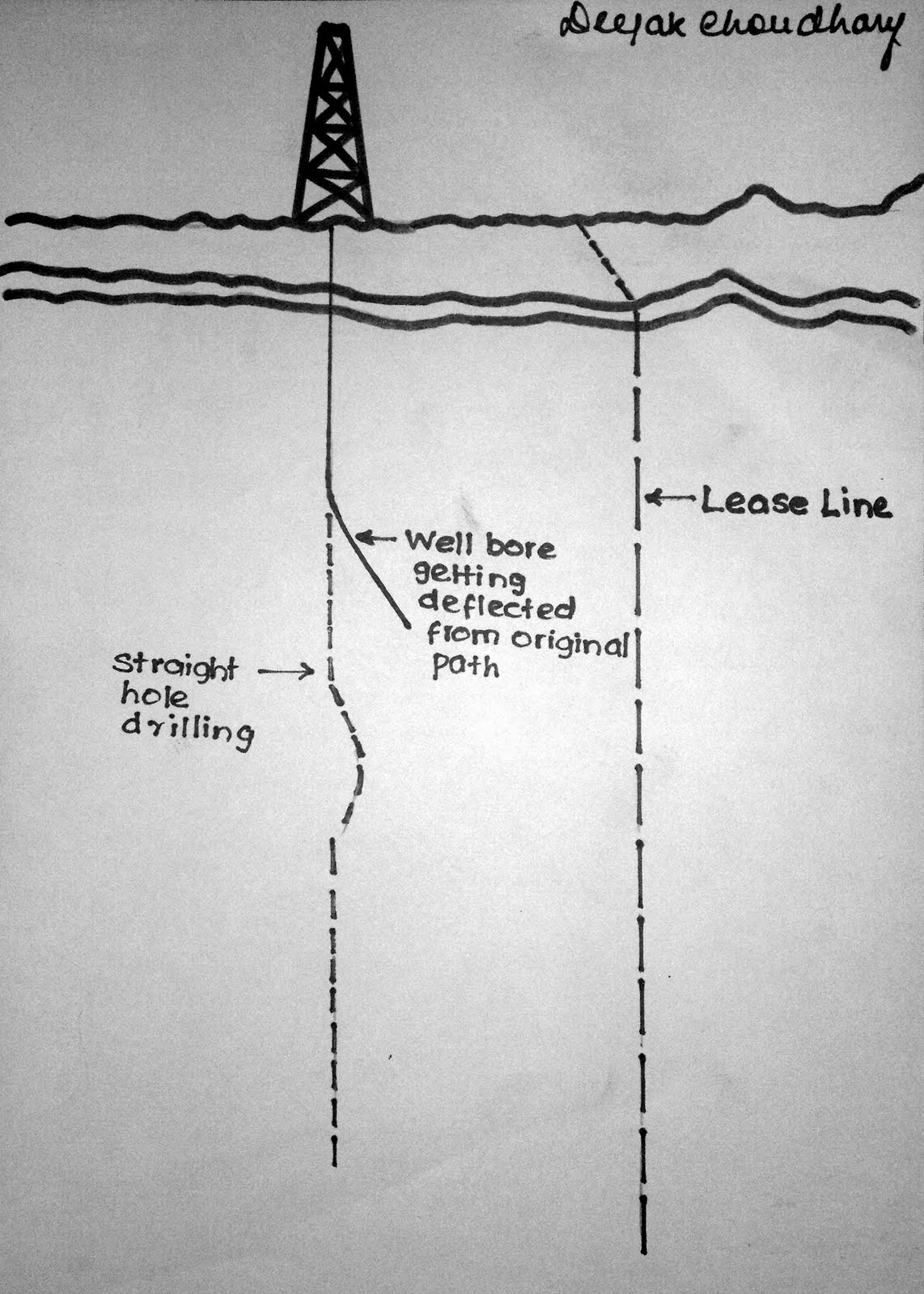
2. STRAIGHT HOLE DRILLING
Straight hole drilling is a special case of directional drilling where an attempt is made to keep the hole vertical. Some reasons for wanting to keep the hole vertical are:
a.To keep from crossing lease lines;
b.To stay within the specifications of a drilling contract;
c.To stay within the well spacing requirements in a developed field (Figure below).
 |
| Straight hole Drilling |
3. CONTROLLED DIRECTIONAL DRILLING
Controlled directional drilling is used when drilling multiple wells from an artificial structure such as offshore platforms, drilling pads, or man made islands (Figure below). The economics of building one offshore platform for each well would be prohibitive in most cases. However, since wells can be directionally drilled, forty or more wells can be drilled from a single platform. Without controlled directional drilling, most offshore drilling would not be economical.
 |
| Multiple Wells from an Artificial Structure |
4. DRILLING MULTIPLE SANDS WITH A SINGLE WELLBORE
There are special cases when multiple sands are drilled with a single wellbore. Where steeply dipping sand zones are sealed by an unconformity, fault, or salt dome overhang, a number of vertical wells would be required to produce each sand, which are separated by a permeability barrier. However, all the sand zones can be penetrated with one directionally drilled well thereby greatly reducing the cost of production (Figure below).
 |
| Drilling Multiple Sands from a Single wellbore |
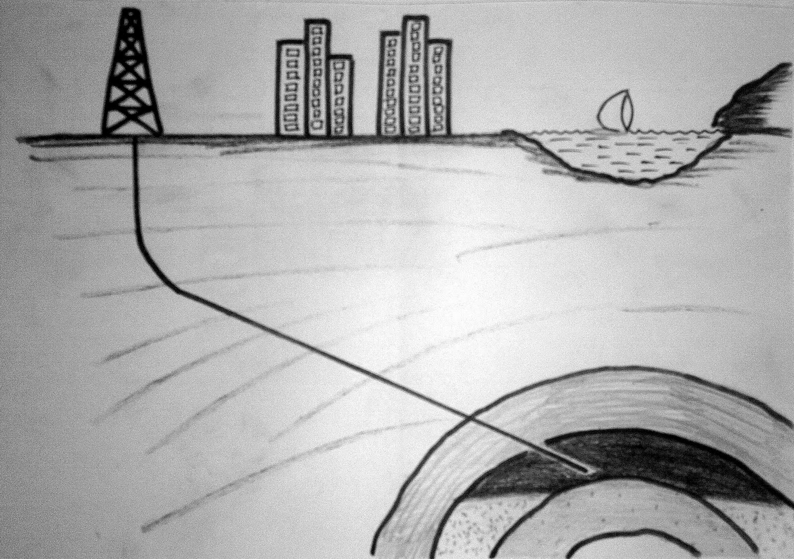
5. INACCESSIBLE LOCATIONS
There are times when oil deposits lie under inaccessible locations such as towns, rivers, shorelines, mountains, or even production facilities (Figure BELOW). When a location cannot be constructed directly above the producing formation, the wellbore can be horizontally displaced by directional drilling. This allows production of an otherwise inaccessible hydrocarbon deposit.
 |
| Inaccessible location |
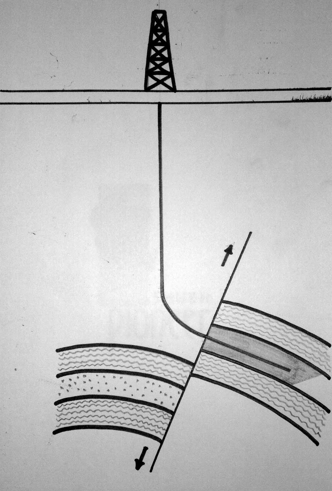
6. FAULT DRILLING
Directional drilling is also applicable in fault drilling (Figure BELOW). It is sometimes difficult to drill a vertical well in a steeply dipping, inclined fault plane. Often, the bit will deflect when passing through the fault plane, and sometimes the bit will follow the fault plane. To avoid the problem, the well can be drilled on the upthrown or downthrown side of the fault and deflected into the producing formation. The bit will cross the fault at enough of an angle where the direction of the bit cannot change to follow the fault.
 |
| Fault Drilling |
7. DRILLING SALT DOME REGION
Many oil fields are associated with the intrusion of salt domes. Directional drilling has been used to tap some of the oil which has been trapped by the intrusion of the salt. Instead of drilling through the salt overhangs, the wells can be directionally drilled adjacent to the salt dome and into the underlying traps as shown in Figure BELOW. However, since the development of salt saturated and oil based muds, the amount of directional drilling has decreased. It is difficult to drill long intervals of salt with fresh water muds. Directionally drilling around the salt, alleviates a lot of the problems associated with drilling salt.
 |
| Salt Dome Drilling |
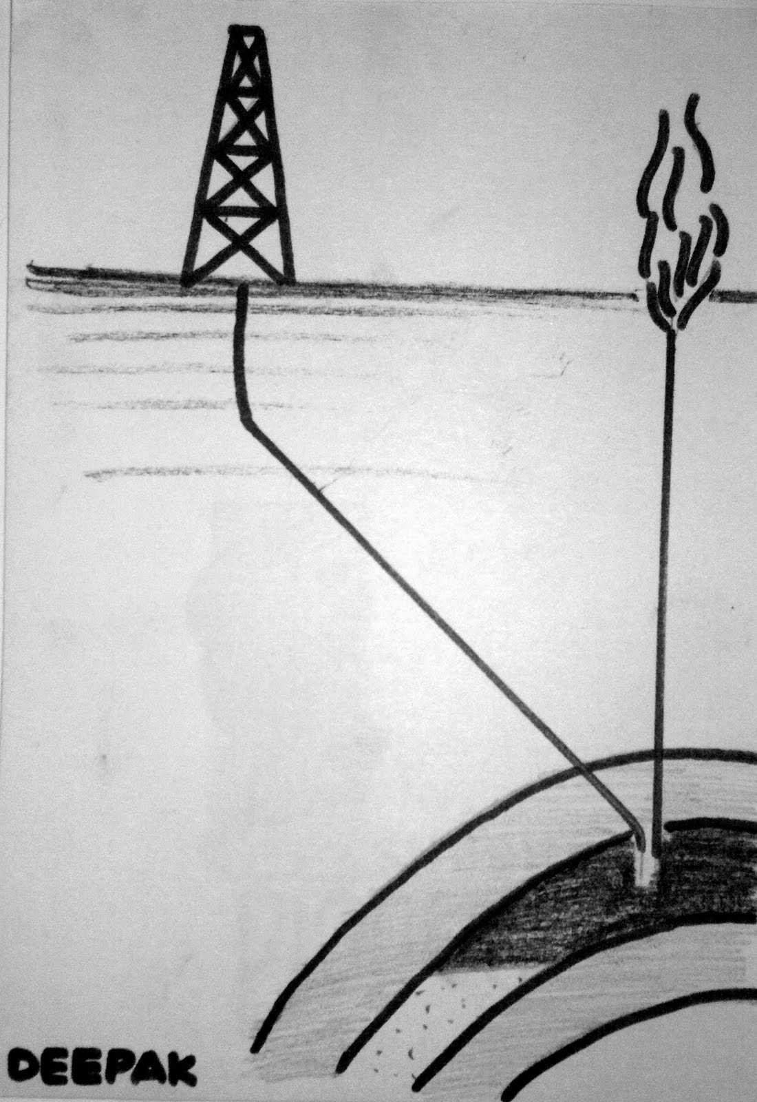
8. RELIEF WELL
A highly specialized application for directional drilling is the relief well. If a well blows out and is no longer accessible from the surface, then a relief well is drilled to intersect the uncontrolled well near the bottom (Figure). Water or mud are then pumped through the relief well and into the uncontrolled well. Since it is sometimes required that the relief well intersect the uncontrolled well, the directional drilling has to be extremely precise and requires special tools. Survey data is not accurate enough to intersect a wellbore at depth. Proximity logging is required when drilling relief wells.
 |
| Relief Well Drilling |
9. DRILLING HORIZONTAL WELLS
Horizontal drilling is another special application of directional drilling and is used to increase the productivity of various formations (Figure below). One of the first applications for horizontal drilling was in vertically fractured reservoirs. In fractured reservoirs, a significant quantity of the production comes from fractures. Unless a vertical well encounters a fracture system, production rates will be low.
Horizontal drilling is used to produce thin oil zones with water or gas coning problems. The horizontal well is optimally placed in the oil leg of the reservoir. The oil can then be produced at high rates with much less pressure drawdown because of the amount of formation exposed to the wellbore.
Horizontal wells are used to increase productivity from low permeability reservoirs by increasing the amount of formation exposed to the wellbore. Additionally, numerous hydraulic fractures can be placed along a single wellbore to increase production and reduce the number of vertical wells required to drain the reservoir.
Horizontal wells are used to increase productivity from low permeability reservoirs by increasing the amount of formation exposed to the wellbore. Additionally, numerous hydraulic fractures can be placed along a single wellbore to increase production and reduce the number of vertical wells required to drain the reservoir.
Horizontal wells can be used to maximize production from reservoirs which are not being efficiently drained by vertical wells.
 |
| Horizontal Drilling |
10. DRILLING MULTILATERAL WELLS
Directional drilling can also be used to drill multilateral wells. Multilaterals are additional wells drilled from a parent wellbore as illustrated in Figure 1-11. Multilaterals can be as simple as an open hole sidetrack or it can be more complicated with a junction that is cased and has pressure isolation and reentry capabilities. Multilaterals are used where production can be incrementally increased with less capital costs. Multilaterals can be used offshore where the number of slots are limited. It is also used to place additional horizontal wells in a reservoir.
|
| Multilateral Wells Drilled From a platform |
11. EXTENDED REACH DRILLING
Another application of directional drilling is what is commonly termed extended reach drilling. As illustrated in Figure below, extended reach drilling is where wells have high inclinations and large horizontal displacements for the true vertical depth drilled. Extended reach drilling is used to develop reservoirs with fewer platforms or smaller sections of a reservoir where an additional platform cannot be economically justified. Extended reach drilling will become more popular as the cost of platforms in deeper water and severe environments becomes more expensive.
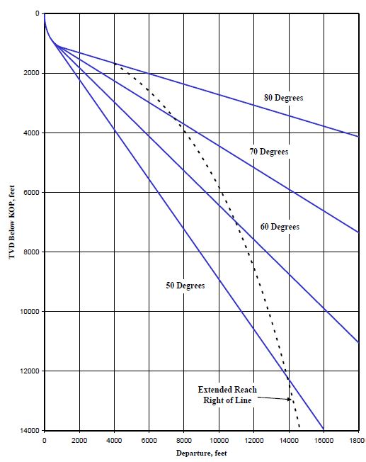 |
| Extended Reach Drilling |